Q Which size combiner should I purchase?
A As a general rule, you can use the Combiner 100 for alternators rated up to 100 amps, the Combiner 160 for alternators rated up to 225 amps and the Combiner600 for alternators rated up to 600 amps.
If you contemplating upgrading alternator size in the future it makes sense to get the larger combiner in anticipation.
If your battery bank is large - out of proportion to your alternator size - this is another reason to go up in Combiner size.
Q Can I combine banks of different sizes?
A Yes, since the starting bank is typically smaller than the house bank, this is a common situation.Q Are the Combiners compatible with LITHIUM batteries?
A The Trollbridge 24 is compatible with Lithium batteries. For the Combiners and other Trollbridges you need to select Lithium compatible models with the "-L" suffix currently in field testing and should be available about December 1 2019.Q Will banks of different sizes get fully charged?
A Yes, since the combiner just places batteries in parallel, they are all at the same voltage. The charge level of each battery is a function of voltage, so they will all receive the same level of charge. The actual charge capacity is governed by their size, age, chemistry and condition.Q If I have a long wire run to the batteries, is it OK to shorten the combiner leads?
A In general the answer is no. The leads extending to the batteries are usually quite heavy in order to carry starter motor currents however this is not always the case. So long as the circuit from one bank, through the combiner, and back to the other bank, has a wire size equal to or smaller than the required one, it will be OK to use this one to limit current and you can modify the leads going to the combiner. Keep in mind, however, that shortening the leads on the C100 may void the warranty if it has a contact failure as a result.Q Why do your instructions say not to switch or fuse the alternator sense wire?
A Here is the 25 cent education on alternator sense wires:-The external regulator sense wire tells the alternator regulator what voltage is being produced. If this voltage is less than what is required for charging, the regulator increases the voltage output until the desired value is reached. As the battery charges and the voltage increases, the sense wire now tells the regulator that the voltage has risen too high so it in turn reduces alternator output to keep it constant.
If, for any reason, the external sense wire is not connected to the output of the alternator, the information coming back to the regulator will be incorrect. They usually put a resistor inside the regulator which connects it to the output so usually no harm will occur but if this disconnected sense wire were to be accidentally connected to a low voltage or the wrong battery, the alternator would start increasing its voltage to alarming values trying to raise the voltage on the sense wire. Depending on the smarts of the regulator, the output can get to over 100 volts, however the battery load would limit this until the batteries fry. The dangers are obvious 1. overcharging the battery 2. overvoltage on 12 volt system components, 3. burning out the rectifiers in the alternator.
When you use a battery ISOLATOR, it has a built in diode voltage drop of about 0.6 volts, even when no current is flowing. This makes a significant difference to the charge accepted by the battery. To overcome this, the external sense wire can be connected directly to the battery so the alternator will raise it's output by the 0.6 volts to get the sense wire up to the correct full charge voltage.
In simple installations this will work OK but typically in boats or RVs, with selector switches and multiple battery banks, it is a disaster waiting to happen. If the sense wire is switched to the starting battery, and the alternator on the house battery then the house battery will be overcharged. The owner sensing something is wrong turns the alternator selector switch off, now disconnecting the battery load from the alternator. The sense wire is still calling for charge so the output of the alternator (now without any load) raises to over 100 volts with all the house battery items - electronics, lamps, instruments, etc., still connected to it!!!
So the fewer switches, fuses, wiring or anything that can cause the wrong voltage to come back on the sense wire, the safer in general you will be. This, in essence, is one of the main advantages of a COMBINER over an ISOLATOR. In combiner hookups, the alternator is directly connected to one of the batteries with no diodes in between which introduce a voltage drop or which can open circuit (or short circuit) on overload. Since it is a direct connection, there is no longer any need to bring the sense wire out to the battery so the whole setup is much safer.
Q Can I combine banks of different battery types?
A So far as the combiner is concerned you can however it is not good practice for achieving optimum charge to mix different types since they require different charging voltages. They will eventually get fully charged but it may take a few minutes longer with the charger optimized to the lowest voltage battery.You can, however, use a Combiner as a regulator if your starting battery is lead-acid and the alternator is internally set for lead-acid voltages. This saves scrapping the good starting battery and the cost of modifying the alternator and adding an external regulator. HOW TO CHARGE AN AGM OR GELL BATTERY ALONG WITH A LEAD-ACID BATTERY.
Q Can I parallel multiple batteries into one bank or do I need a combiner for each battery? ?
A You can parallel batteries to increase the size of a bank. In general you should attempt to use as large a capacity battery as is practical to minimize the number of batteries permanently connected in parallel. The risk when increasing the number connected in parallel is that if one battery has a bad cell, it will become a load on the other good batteries and discharge them as soon as you cease charging. To minimize this risk, batteries placed in parallel should be of the same age (preferably new) and same manufacturer and model so that the chance of one dying early is reduced. Providing disconnect switches on each battery of a multiple battery bank will allow simple and rapid isolation of each battery to monitor for bad cells.Q Can I combine one bank of new batteries with another bank of old ones?
Q Can I combine a bank of one brand with a bank from a different manufacturer?
Q Can I parallel old and new batteries within one bank?
Q Can I parallel different size batteries within one bank?
When the old one eventually dies, it will drag the new one down but this happens whenever two batteries are in parallel and one dies, the only difference here is it is going to happen sooner than it would had they both been brand new. So big deal, you gained some residual use out of the old one and the new one will not be permanently damaged - just charge it up again.
The bottom line is the batteries in parallel provide more power - never less - than either one on its own - it just may not be the "ideal" way to do it.
Q Won't the smaller battery get overcharged if put in parallel with a large one?
A The whole process of charging batteries in parallel is naturally self regulating, naturally governed by terminal voltage and current flowing through the internal equivalent resistances. For simplification, each battery can be considered as a perfect battery that holds the charge combined with a series resistor representing the internal resistance, and a parallel resistance representing the self-discharge leakage current.Lets say you have a charging source dumping out say 100 amps. If you have 4 batteries in parallel sharing this source the distribution of the charge current is governed by those internal voltages and internal resistances. From Ohm's law, the charging current that flows into each battery is the voltage divided by the resistance. In this case the voltage is the charging voltage arriving at the terminals minus the actual internal voltage divided by the series resistance of the battery. A discharged battery is going to put a larger voltage differential over the internal resistance so more current will flow to it. A charged battery is going to put less voltage drop across the internal resistance so it will take less or none of the available charging current. A large plate battery which has a correspondingly lower internal resistance will demand more current because of this lower resistance. A small motorbike battery in parallel will have a high internal resistance and demand very little current.
All these demands for current result in a common voltage on the parallel circuit which is what the alternator or charger sees. None of the batteries will ever be "overcharged" as a result because the charging voltage is controlled. Even the smallest battery will only be seeing the same voltage so it is like the other batteries are not there. If you suddenly removed all the big ones and left just the tiny bike battery on the 100 amp alternator, the regulator in the alternator cuts the current back to a level that limits charging to a safe level.
Q What happens if two alternators end up charging the same banks?
A Let's dispel the myths of multiple battery charging sources.So what happens when there is more than one charging source is all those regulators that see a voltage less than the (next) threshold, charge the battery as though the other charging sources weren't there. They don't "know" anything else is charging. During the bulk charge, when the battery voltage is below all the thresholds, all the sources will be putting out the maximum they can. As each charging source reaches a threshold it changes its charging rate accordingly. Since no two regulators will have exactly the same threshold(s) this means that some of the paralleled regulators will tend to cut down or shut down before others and leave the job of finishing the charge to them but by that stage the current requirements are within the capacity of the one(s) that continue(s) to remain on line.
Despite cries of doom, especially from outboard motor manufacturers, we have had customers using Combiners to parallel battery banks with multiple alternators and other charging sources since 1993 without a single feedback situation of any problems.
Q Is the 6 gauge wire recommended for the 160 amp combiner heavy enough?
A Yes, in fact this is a MAXIMUM size, using a heavier gauge can damage the combiner. See the following question for more information.Q I installed a 100 amp combiner on my boat which has a 90 amp alternator. Last year the contacts welded shut so I replaced it but now it has happened again. Should I have used a 160 amp combiner?
A No, the 100 amp combiner is probably adequate. Typically only a portion of the current flows through the combiner because the charging source is connected directly to one of the banks. Your problem is most likely that the installer did too good a job and did not follow the installation instructions. The intuition that bigger is better applies to most installations, however it can kill a combiner. The instructions for the 160 amp combiner recommend a minimum wire run from the battery of 3 feet to each combiner terminal and recommend a wire size no heavier than 6 gauge. The leads come already attached with the 100 amp combiner which must not be shortened. This wire has a negligible resistance to the normal charging current and has zero voltage drop as the batteries reach full charge but it does have enough resistance and inductance to prevent the contacts welding when the batteries being combined are at different voltages and one battery is supplying high power to the other for a few seconds.Q My batteries are over 20 feet apart. Can I connect the combiner to the existing selector switch instead of directly to the batteries?
A It is OK to connect the combiner at the selector switch if you already have heavy duty cables from the switch to the batteries. You must still observe the wire size and length limitations that come in the instructions for the connection between the combiner and the switch terminals. Using a heavier gauge, or a shorter length will remove the protection that this very small resistance provides to the contacts.Q Why does my 'Combined' light stay on when charging is completed?
A Even though charging is complete, if the charger is still on it will maintain a high enough voltage to keep the banks combined. If you have just discontinued charging, the float voltage may still be high enough to keep the combiner on for quite some time, or there may be a forgotten source of charging (Inverter?. Solar? Shore power?) To test it, use a fairly good quality voltmeter and measure the voltage from the ground terminal right on the combiner connection to each of the battery leads going to the combiner. If all read less than 12.8 volts and the unit remains combined for over 30 seconds or it is pulsing, it is faulty and should be replaced.Q ABYC standards recommend installing fuses or circuit breakers between the combiner and the battery banks. Are they really necessary and what size should I use?
A Marine wiring practice guidelines say that all 12 volt circuits except starter motor leads should be fused. Ideally starter motor leads should also be fused, however since the emergency loads required by a starter motor can approach (or exceed) the maximum output of the battery a fuse which would blow on the short circuit current available from the battery, could also blow when the starter motor was in use.There is an internal fuse to the ground connection in the Combiner so the fuses in the battery leads to the combiner are mainly protection against a metallic object shorting a combiner terminal to ground or a battery lead from the combiner being removed and allowed to contact a grounded object. These are both conditions which could occur on the starter motor but which do not normally have any protection.
The necessity for battery lead fuses to the combiner should be decided on an installation basis. If the combiner is mounted where shorting the terminals to ground is virtually impossible then you may decide to take the risk. If it is a steel boat and the combiner is surrounded by grounded metal the risk of a short is much higher and fuses may be a good protection. The size of the fuses has to be much higher than the combiner current rating because when the combiner first closes, quite large currents can flow from one battery to another. If you have followed the installation instructions, these battery to battery currents are limited by the minimum wire run and maximum wire gauge specifications recommended. The combiners can survive 4 times their rated capacity for a short period of time so the fuse should have at least this capacity. Even larger currents can occur for milliseconds after the contacts close so a "Slow Blow" fuse should be used so it can survive these. Although the risks are minimal without a fuse, the results of an accident can be catastrophic and even life threatening.
ABYC standards also call for battery circuit disconnect switches located electrically close to the positive battery terminal to allow isolation for emergencies and regular maintenance.
Q How do I connect a third bank using an extra combiner?
A Typically you will have the engine alternator charging the starting battery and perhaps a shore power charger or inverter charger charging the house battery. You can connect an extra bank through a Combiner from either of these batteries.If the auxiliary battery is connected to the house battery using a Combiner, it will have to wait for the house battery to get to 13 volts or more before it can charge. If connected to the starting battery it will have the same priority as the house battery. See the question on size selection.
Q Do I need a heavy gauge cable to run from the engine to the rear battery of my motor home?
A Not really. The voltage drop along the recommended size cable (6 gauge for C160, 10 gauge for C100) is quite small. As the charge nears completion, this current drops down to zero so the voltage drop drops to zero also and a full charge is reached. In the special case where the lead to the rear of the vehicle is also being used for starting engines in emergency or being used when the engine is off to operate a load using power from the house battery, then a heavier conductor would be necessary for carrying these load currents. In this case you should still use the recommended gauge and minimum length of wire to connect between the starting battery and the front end of the heavy gauge wire going to the rear battery bank in order to protect the combiner.Q Is the cut-in/cut-out voltage adjustable?
A No. The voltage setting is done by precision components without the use of potentiometers which are notoriously unreliable in locations subject to vibration. By eliminating the wiping contact the combiner has improved stability and reliability at the expense of not being adjustable. Typically a battery will have a float voltage of about 13.6 to maintain full charge so the combiner should always be closed.Q Do you make a 24 volt version?
A No, you should use the Trollbridge12X24 which charges a 24 volt battery from a 12 volt alternator.Q After I start charging why doesn't the "Combined" light come on?
The combiner detects that charging is present by measuring the voltage on the battery that is receiving the charge. When you first start, the battery voltage is below the combiner switching level of about 13 volts so the combiner doesn't close until the battery has received enough charge to reach this voltage. This happens quite rapidly but depending on the battery size and alternator size, it can take a few minutes. There is also a 30 second delay on all switching to prevent rapid cycling on temporary voltage changes.
The most likely reason the combiner is not turning on is the voltage is not high enough. On the Combiner 160 you can check this with a digital meter connected to the ground and each of the + terminals. On the Combiner 100 measure on the end of the ground lead and each of the positive leads. If the voltage measured here is not above 13 volts on at least one of the terminals, the combiner is not going to turn on. Check the following reasons for low voltage during charging:-
Q Is is OK for the combiner to cycle off and on when charging first starts?
A This is normal. When one battery gets to about 13 volts and the combiner closes, it is connecting it to a battery which may be at only 12 volts. High current will flow from the 13 volt to the 12 volt one. This causes the voltage on the 13 volt to drop despite the charging current from the alternator so after a 30 second time delay, the combiner turns off. By this time both batteries will be at an intermediate voltage, for example 12.5. So the battery on charge starts building up to 13 again and eventually the contact closes and delivers another pulse for 30 seconds to the other battery. After a few cycles like this, the battery receiving the charge via the combiner will be charged high enough that it will stay on continuously. This cycling is a protective function for both the batteries and the combiner so that the excessive currents from putting the batteries in parallel does not cause overheating. The high current pulses can even be beneficial to batteries which sit for long periods with negligible loads.Q Why doesn't the combiner work in my twin engine boat?
A It appears from your drawing that the negative side of your batteries on each engine are not connected together. If you whish to use the other engine's battery for starting via the selector switch, or to be able to charge the other engine's battery through the combiner, you have to provide a return path for the current to the negative side. This should be a heavy duty lead, at least as heavy as the leads to the starter motors joining the negative side of each battery. It can be installed from engine block to engine block if that is more convenient. Without the grounds connected together you risk all sorts of damage, especially if the ground current tries to return through your throttle or gear change cables which could overheat and cause a fire.Q Will the combiner be damaged if I start an engine while it is closed?
A No. This question assumes a shore charger is on and the batteries are combined when you go to start the engine. Current will be supplied directly from the starting battery and also through the combiner from the house and other batteries. This current is limited the same way as the inrush current when two batteries are placed in parallel, which is by the minimum length and maximum size of the wire as specified in the installation manual.In fact the problem is less severe since the contact is already closed and does not have to actually make the connection, just carry the current which it will do quite well. We have provision on the combiners for manually closing the contact with a remote control to provide help for emergency starting. The help it provides is limited, however, by the wire gauge and length although transfer of energy from the house to the starting battery can often give the boost needed if the starting battery is very low, when added to the current coming through the combiner during starting.
Q How do I connect a multi-ouput shore charger when using combiners?
A It really doesn't matter. If you connect one output to each battery the combiner(s) will close fairly soon after charging starts because the starting battery will usually not require much power and will come up to the switching voltage rapidly. The combiner will then help charge the house battery with the excess power not required by the starting battery. If most of the charging is being required by the house battery you might connect all the outputs together on it and allow the combiner(s) to top-off the charge on the starting battery(s)Q I can't see the "COMBINED" LED. Do you have a remote indicator?
A We had a prototype on field test for about a year but consumer demand was too low to put it in production. It can be fitted to any Combiner. It consists of a push-button with a built in LED. The LED will turn on when either battery is above the switching voltage but before the time delay of the combiner to give an instantaneous voltage monitor. For example it might go off for a few seconds while you start an engine even though the combiner stays closed due to its time delays.The push button will manually close the combiner to parallel the batteries for emergency starting. After pressing it, the combiner will stay closed for a minute or two then return to automatic operation so you can't forget and leave it on.
In response to a request, we are making the design information available so you can make your own. It is not a project for beginners - it requires some knowledge of components, soldering skills, and you have to develop your own packaging. The circuit diagram and some construction information is on the second page. DOWNLOAD INSTRUCTIONS IN PDF FORMAT FROM HERE.
Q Combiner didn't turn on until I got to 14.2 volts while bench testing, what's wrong?
A As you were raising the voltage on the power supply you used for testing, the combiner actually started to turn on at 13 volts but there is a turn-on time delay. During the time delay you were continuing to increase the voltage because it had not turned on so when the time delay ended you had reached 14.2 volts. Because of the time delays, it is virtually impossible to measure the trip voltage in this manner.Q I have a very simple outboard setup. Can I omit the switches?
A Yes, you can simplify the setup considerably, especially where there is no dry space for installing battery selector switches. The simplest setup would be to add an extra battery to a conventional single outboard motor with existing starting battery.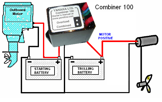
WARNING: Creating sparks when connecting to a battery that has been on charge can cause a dangerous explosion. Make sure the device you are connecting is turned off as you make the connection.
Q Which terminal goes to the starting battery and which to the house battery?
A It does not matter which terminal you use for which battery. The combiner is bidirectional which means that it doesn't matter which battery is being charged, it will close in either case and allow the other battery to share the charge. So if you have a 115 volt shore charger or an inverter with a charger built in, connected to the house battery, it will also automatically charge the starting battery.Q Why does my "Combined" light go off while charging is still proceeding?
A Any time the voltage on both batteries remains below about 13.0 volts for more than a minute the combiner turns off. There are many reasons why this may happen:-Q Why does the combiner CHATTER when I stop charging?
A The Combiner should never chatter, check the installation for loose connections and if they look OK, it will be replaced under our unconditional warranty.